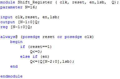
Shift Register Verilog Code

First of all, don't forget your begin- ends around sections of code: else beginrreg0=data;rreg = rreg. Your implementation produces quite a different output from the book's. You should prove this to yourself by constructing a simple testbench to drive your inputs and run a simulation. Nasi goreng jawa larasa. You will see that the book's output shifts the input data by a single clock cycle, whereas your output shifts the input data by eight clock cycles.By the way you have indented your always block, I am led to believe that it is not what you wanted.
Verilog Shift Operator

VLSI - Universal Shift register in Verilog Code. Here is the code fo Universal Shift register in Verilog. This is a parallel shift register. It can shift left & right controlled by 'lrb'. It simultaneously shifts data out from lsb & sotres input data from din to lsb, if lrb=1 which is shift left. And vice versa for right shift. So, one shift register. And synthesisable. Your mission, should you choose to accept it, is to modify the Verilog code to create a.
This is how your block really behaves: always @(posedge clk or negedge reset)beginif(!reset) beginrreg =0;end else beginrreg0=data;endrreg = rreg.
IntroductionThe shift registers store a value and shifts it. They are extremely useful. They are used to convert information from parallel to serial (and vice versa) for use in syncronous communications. Communications through SPI, I2C, and more are implemented with these registers. The also allow us to perform the operations of multiplying by powers of 2 and dividing by powers of 2 for integers.In this chapter we will use them to generate a sequence of 4 states on the LEDs of the iCEstick, moving the lights clockwise.Description of the register.The shift register we will use is as follows:The output of the register is N bits (in our example we will use a 4 bit register). It has an N-bit Parallel input, which allows us to load the register with a new value.
Siso Shift Register Verilog Code
The loadshift signal allows us to determine the operating mode: when it is at 0, a new value is loaded when a rising edge of the clock arrives. When it is at 1, a right shift is made on the rising edge of the clock.In this shift the most significant bit is lost and the new value is read from the serin input (serial input). If we have the initial value 1'b1001 stored, and the signal loadshift is at 1, while serin is at 0 and a rising edge of the clock arrives, we get the value: 0010. On the next cycle (if serin statys 0) we get 0100, then 1000, and then 0000.shift4: Rotation of bitsAs an example we will use a 4-bit shift register to rotate a sequence of bits and display them by the 4 LEDs on the iCEstick. The sequence obtained by the LEDs will depend on the initial value loaded in the register.The block diagram of the shift4 component is:The main component is a 4-bit shift register. It's clock input is connected to the iCEstick clock via a prescaler component to lower it's frequency and to be able to see the shifting of the bits in the LEDs.The most significant bit of the register ( data3) is connected directly to the serin input, so that bit rotation is achieved (the most significant one becomes the least significant).Via the parallel input we introduce the initial value, which by default will be 1'b0001.
Universal Shift Register Verilog Code
Rotation will show the sequence 0010, 0100, 1000, and 0001.The initial load is done using an initializer, as shown in chapter 9. It is connected to the input loadshift, so that initially it is 0 and when the first clock edge arrives it changes to 1, loading the initial value and changing to shift mode. The rest of the cycles will be shifting. This is an example of how the initializer works.Hardware DescriptionShift RegisterThe shift register is described with very few lines. It is a process that depends on the rising edge of the clock.